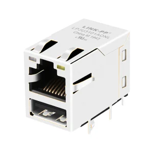
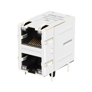
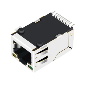
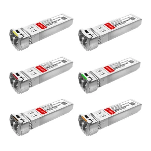
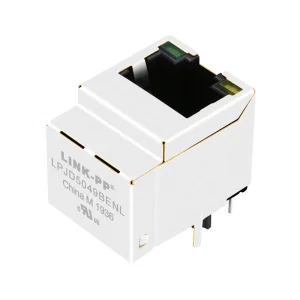
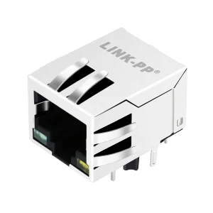
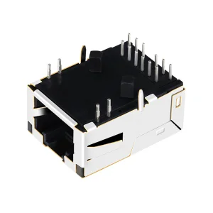
Engineered to exact OEM specifications, featuring robust EMI shielding, high signal integrity, and broad optical module compatibility.
In modern communications architecture, physical layer reliability determines system uptime. The RJ45 interface, originally standardized under registered jack specifications, has evolved into highly engineered coupling devices capable of handling 10 Gbps and beyond. As data centers, industrial operations, and enterprise networks transition to higher frequencies, standard modular interfaces must adapt to combat electromagnetic interference (EMI), radio-frequency interference (RFI), insertion loss, and alien crosstalk.
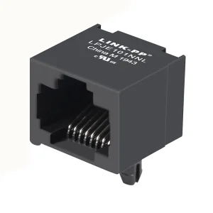
A high-performance RJ45 coupling device acts as a bridging element, maintaining electrical continuity and shield integrity across copper links without degrading signal performance. Achieving this level of reliability requires advanced material sciences and physical geometry optimizations, specifically focusing on contact engineering, spatial shielding, and PCB traces configuration.
Every discontinuity in a transmission line causes reflection of the electrical signal, measured as Return Loss. In Cat6a and Cat8 configurations, maintaining a constant 100-ohm differential impedance through the coupling contact point is critical. Advanced RJ45 coupling units mitigate signal loss through:

In noise-heavy industrial environments, such as factory floors with variable frequency drives, or dense server racks packed with switching hardware, unshielded copper links become antennas for noise. Our custom OEM RJ45 couplers incorporate comprehensive 360-degree shielding using nickel-plated brass or copper alloy shells. When mated with shielded patch cables, they form an uninterrupted ground path that shunts high-frequency electromagnetic noise directly to the chassis ground, preserving the signal-to-noise ratio (SNR) required for high-speed transceivers.
Founded in 2016, Novafiber Communications Co., Ltd. has established itself as an engineering-centric optical transceiver and network interconnect manufacturer, delivering highly reliable hardware to data centers, telecom operators, and global integrators.
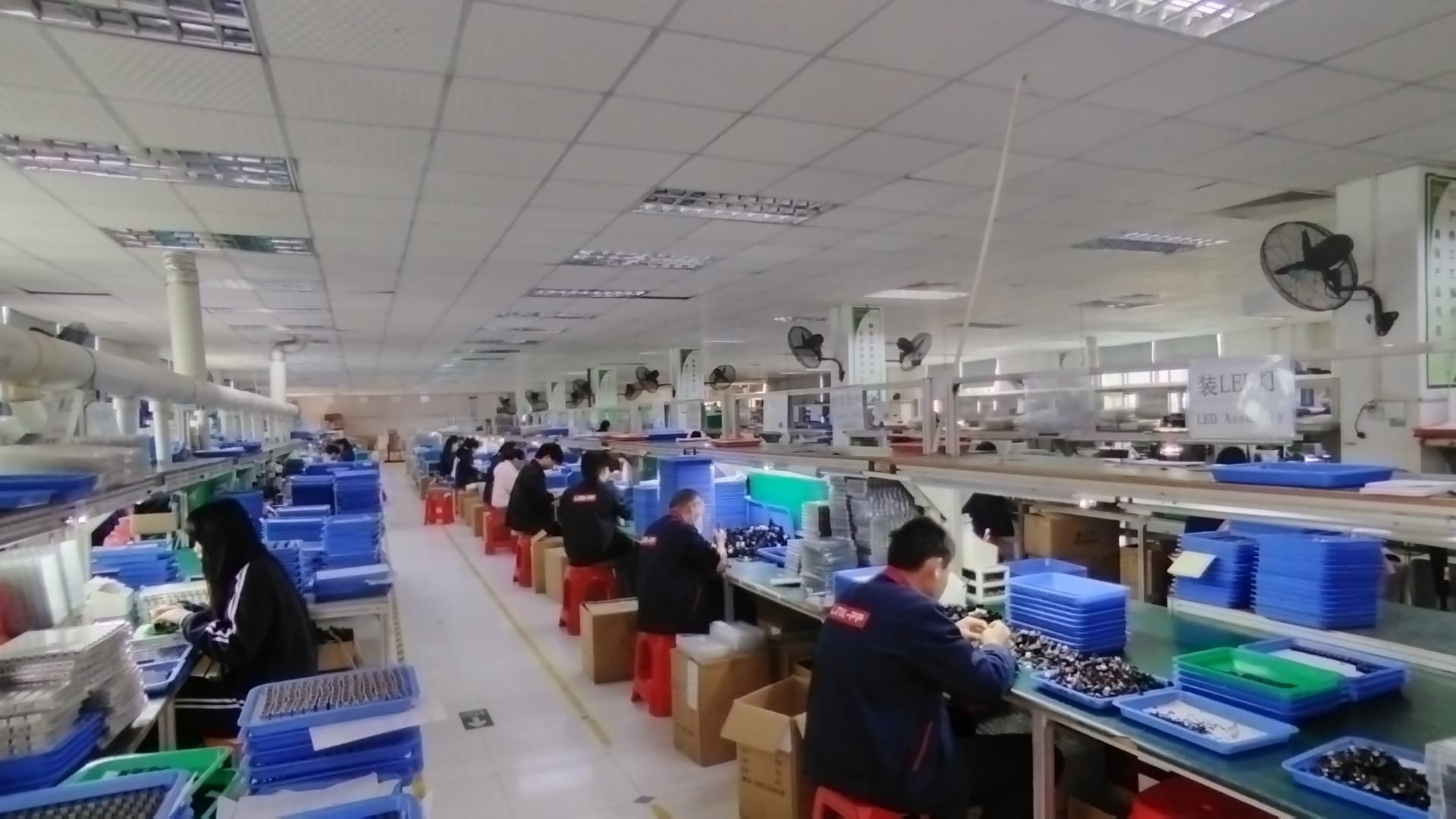
Our 420㎡ specialized testing facility and advanced production lab support rigorous mechanical, electrical, and environmental screening protocols. Novafiber handles complete customized requirements, including:
In the global technology hardware supply chain, maintaining continuous material availability while controlling unit cost is a critical challenge. Novafiber leverages China's advanced industrial ecosystem to offer clients unbeatable security, speed, and design flexibility.
By coordinating with our network of over 1,200 supply chain partners, we streamline the procurement of raw copper alloys, high-performance engineering plastics, precision stamping dies, and automated testing equipment. This deep integration allows us to quickly transition from initial prototyping to high-volume manufacturing, minimizing lead times and protecting clients against supply-side disruptions.
65 dedicated quality inspection personnel enforce IPC standards, automated optical testing (AOI), and environmental stress screening (ESS).
Our engineering team developed and introduced 320 new product variations within the last year, securing our industry-leading R&D positioning.
Zero-defect production logic utilizing high-temperature aging, automated optoelectronic parameter evaluation, and live-traffic loopback tests.
Across Europe, North America, and parts of Asia, we are observing a significant upgrade of edge computing nodes and industrial control centers. High-density interconnect ports must tolerate continuous operation without signal loss. With the deployment of Power over Ethernet (PoE, PoE+, and PoE++), RJ45 couplers are required to handle up to 90W of electrical power. Underestimating the engineering requirements for PoE can lead to thermal stress and contact deformation during unplugging cycles. Novafiber designs solve these concerns by shaping contacts to keep spark damage away from the critical data transmission contact zone.
Take an inside look at our state-of-the-art production environments, precision testing modules, and distribution logistics.
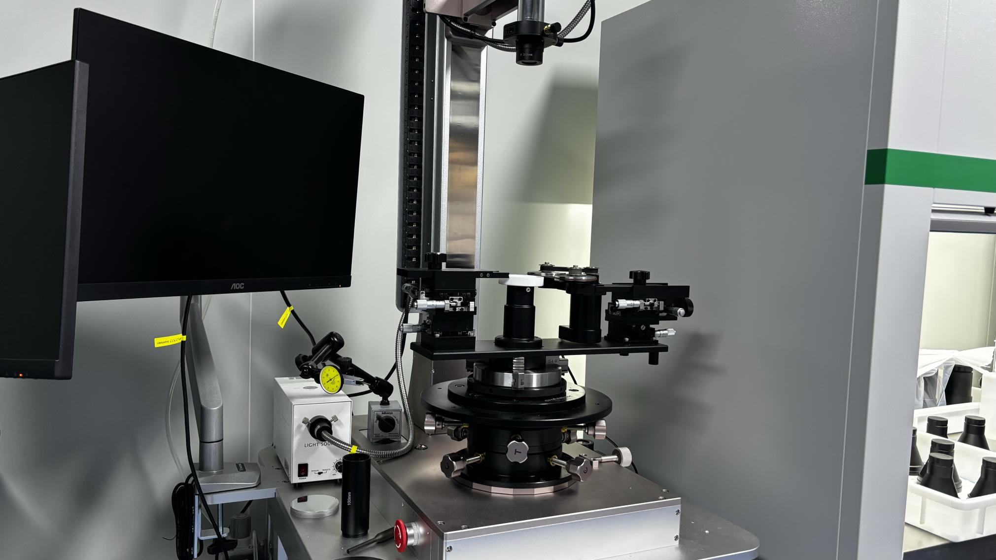
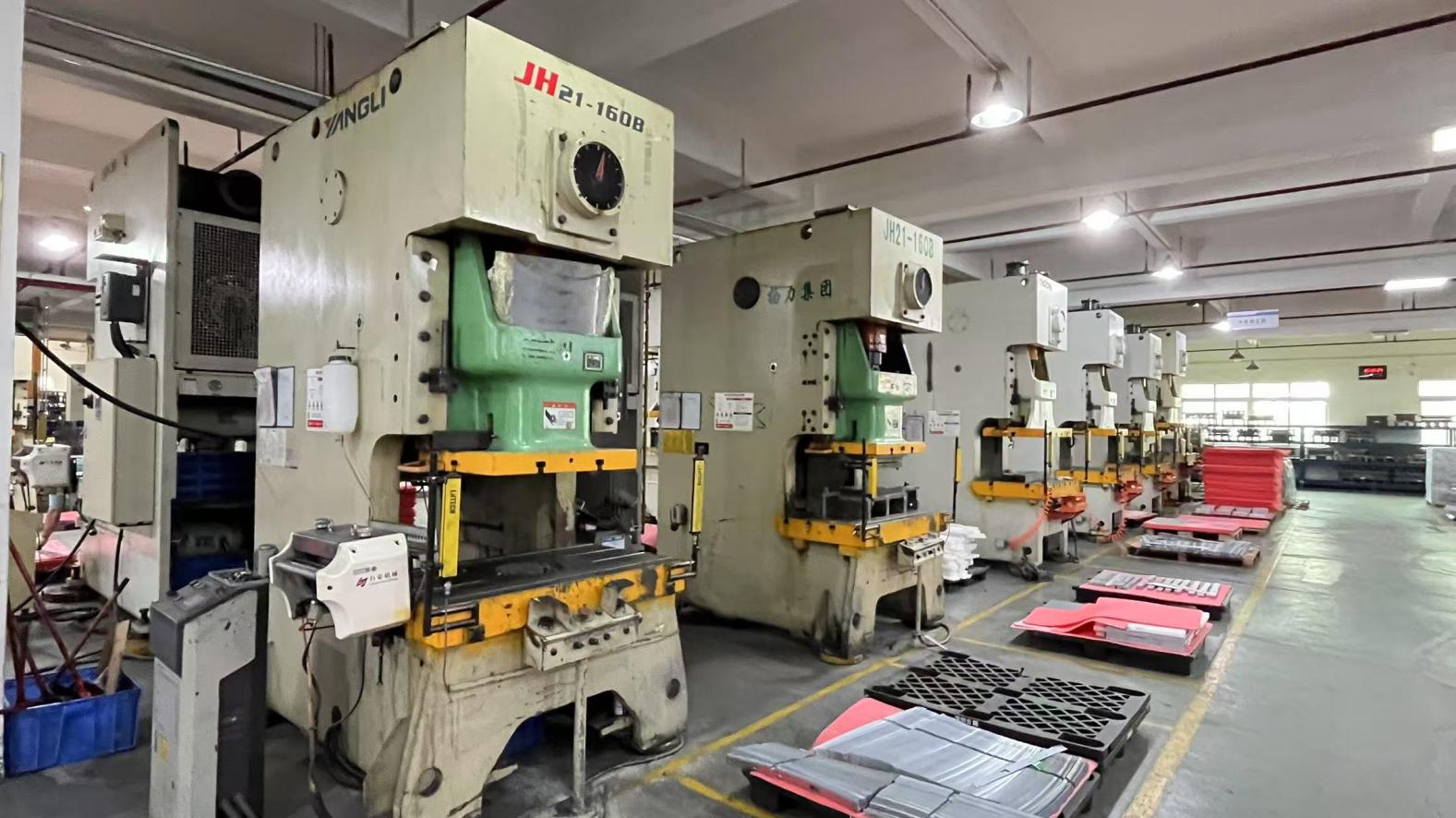
Understanding user intent requires looking beyond the mechanical device to see where it fits in real-world application fields. Our custom RJ45 coupling devices are designed for distinct environments:
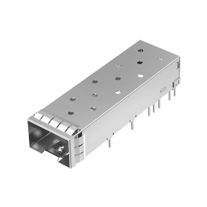
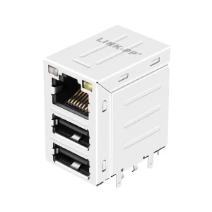
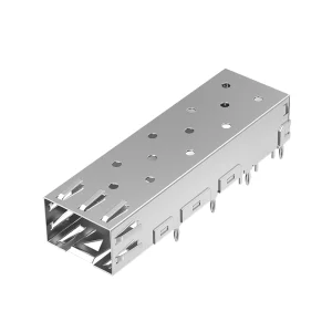
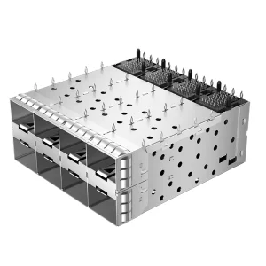
In high-density patch fields, space is premium. Multiport RJ45 connectors and integrated SFP/SFP+ cages with high-frequency capabilities are deployed to support copper-to-fiber conversions and switch interconnect networks. The shielded enclosures prevent crosstalk between closely spaced ports, keeping frame-loss rates at zero.
Vibration, grease, temperature swings, and electromagnetic interference from surrounding motors degrade standard connection jacks. Using reinforced through-hole RJ45 jacks with robust retention clips prevents physical disconnections, while optimized gold plating resists environmental corrosion in harsh factories.
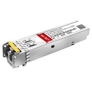
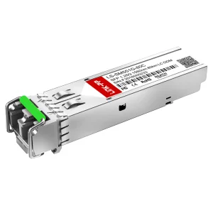
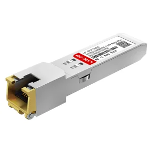
Surveillance cameras, traffic management systems, and outdoor wireless access points require reliable data and PoE paths. Using weatherized RJ45 couplers with integrated transceivers ensures constant network links, protecting sensitive electronic components from static build-ups and power surges.
Our complete collection of high-performance physical layer connectivity hardware designed for global deployment.
Detailed engineering answers to the most common configuration, standard compliance, and OEM design questions.
 Novafiber