Analyzing market trends, scalability requirements, and structural evolutions of physical layers within high-bandwidth networks.
As modern infrastructure accelerates toward digital convergence, the physical medium layer of enterprise networks remains a critical focal point for performance optimization. Industrially designated as structural media distribution modules, CE Certified Ethernet Splitters occupy a unique position in global B2B procurement networks. In factory environments, smart cities, and dense telco environments, deploying dedicated hardware layers avoids the capital expenditure and architectural complexity associated with active switching equipment.
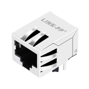
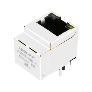
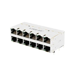
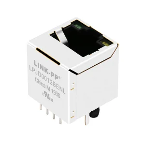
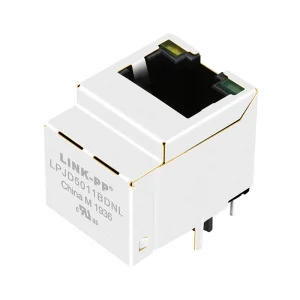
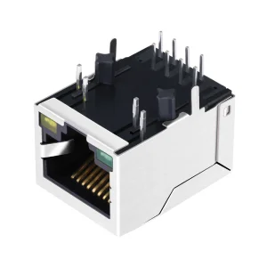
The global demand for high-reliability RJ45 and structural cabling components has shifted. While historical networking favored over-provisioning active network switches, structural cost optimizations, power consumption limits (under global ESG initiatives), and physically constrained pathways (such as cabling inside historic architecture or under-floor conduits) have forced system architects to reconsider the deployment of passive splitting systems. An Ethernet splitter operates strictly at Layer 1 of the OSI model, splitting a traditional 8-position, 8-conductor (8P8C) Category cable run into two distinct physical lines using structured wire paths. This method minimizes structural cable pulls, drastically reducing total copper weight, installation labor hours, and overall spatial requirements in complex installations.
A rigorous engineering examination of standard 8P8C splitting, pinout schemas, and physical transmission constraints.
Standard Fast Ethernet (100Base-TX) operations rely exclusively on two twisted pairs: Pair 2 (Pins 1 & 2 for Transmit) and Pair 3 (Pins 3 & 6 for Receive). A passive physical splitter redirects these circuits. In an 8-pin Category 5e/6 run, the first output connector maps Pins 1, 2, 3, and 6 to their standard positions. The second output redirects the unused copper paths (Pins 4, 5, 7, and 8) to Pins 1, 2, 3, and 6 of the second receiving jack, creating two separate circuits over a single outer sheath.
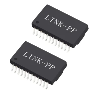
Dividing a single cable jacket into two independent circuits introduces capacitive and inductive coupling hazards between adjacent conductor pairs. Industrial-grade splitters address this using advanced internal PCB trace layouts, shielding isolation barriers, and magnetic decoupling transformers. Minimizing NEXT and FEXT (Far-End Crosstalk) ensures that the return loss characteristics stay well within standard limits, preventing frame drops and physical-layer packet retransmissions.
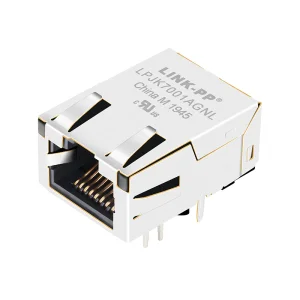
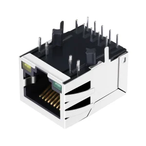
In harsh electromagnetic environments, structural interference from VFDs (Variable Frequency Drives), heavy machinery, and high-voltage supply lines will disrupt signal integrity. High-performance splitters deploy Fully Shielded RJ45 ports (STP configuration) with integrated ground tabs. The metallic shell acts as a continuous Faraday cage, preventing high-frequency noise from penetrating the differential signal paths inside the twisted pairs.
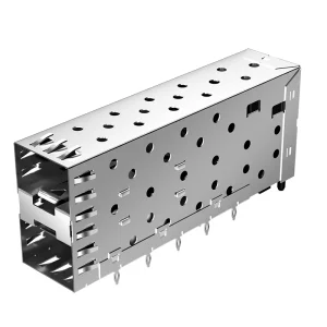
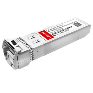
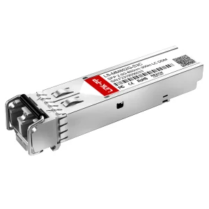
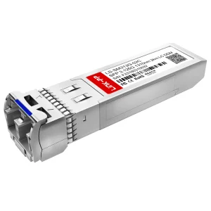
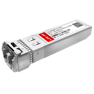
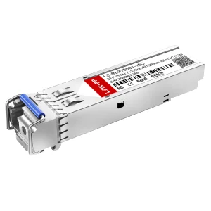
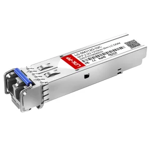
To support high-bandwidth applications, system design engineers must distinguish between passive splitters and active switches. A passive splitter is a fixed point-to-point hardware connection that routes signals without modifying the frame or checking packets. The structural trade-off is clear: while it avoids active device points of failure and operates with zero power draw, it limits the speed of each split link to 100 Mbps (Fast Ethernet), as Gigabit Ethernet (1000Base-T) requires all 8 conductors (4 pairs) to be engaged simultaneously for bidirectional PAM-5 encoded data transmission. For high-speed data centers, specialized SFP modules and active switches are required; however, for IoT sensor nodes, PoE cameras, and auxiliary networks, a 100 Mbps pipeline is more than sufficient and offers significantly higher reliability.
Why regulatory compliance, quality management, and transparent engineering certifications protect B2B infrastructure investments.
For network operators, procurement managers, and system integrators worldwide, regulatory compliance is not a checkbox; it is a critical safeguard. A CE Mark on networking components validates adherence to the strict electromagnetic compatibility (EMC) requirements of European Union Directive 2014/30/EU and the RoHS Directive 2011/65/EU. Installing uncertified networking hardware poses serious operational risks, including:
Deep engineering expertise and state-of-the-art manufacturing facilities serving global network environments.
Novafiber Communications Co., Ltd. is a professional optical transceiver and structured networking component manufacturer specializing in high-performance fiber optic and copper communication solutions for global data centers, telecom operators, and enterprise networking applications.
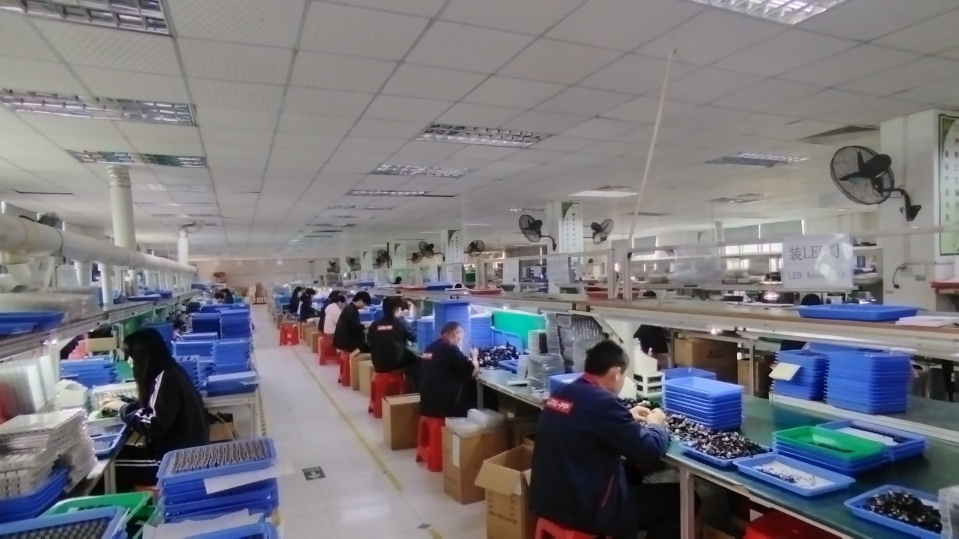
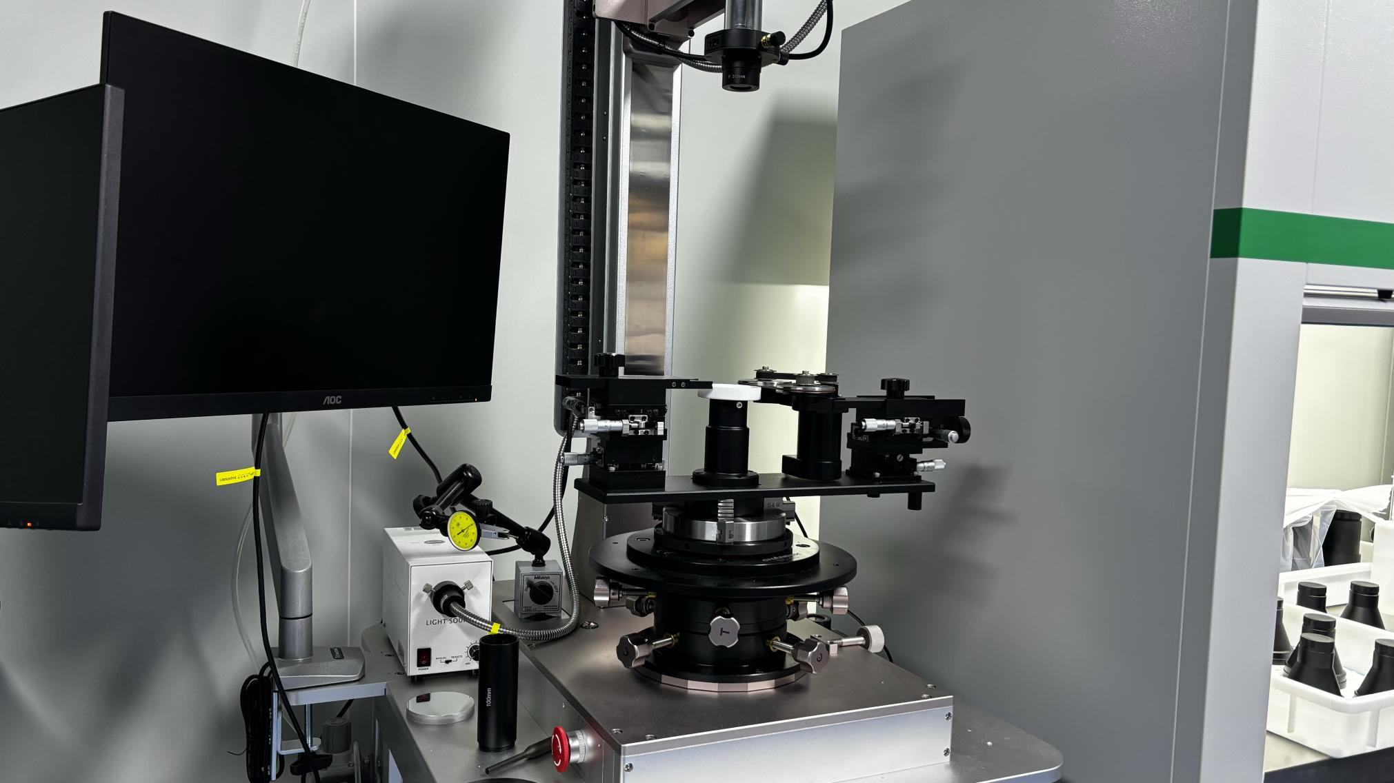
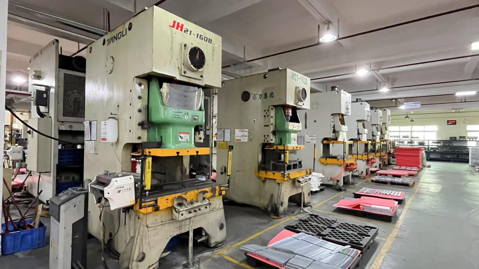
Founded in 2016, Novafiber has developed strong engineering and manufacturing capabilities with a modern production facility covering approximately 420㎡. With over 9 years of industry experience and 7 years of export experience, the company has built a solid reputation in the global optical communication and high-frequency connector market.
Novafiber generates an annual export revenue of approximately USD 8.5 million, serving customers across North America, Europe, Southeast Asia, and the Middle East. The company maintains a flexible and efficient supply chain network with more than 1,200 supply chain partners, enabling stable mass production and fast delivery.
The company employs 65 quality inspection personnel and follows strict quality control systems, including IPC standards, automated optical testing, and environmental stress screening (ESS). Product inspection methods include 100% functional testing, burn-in testing, and high-temperature aging tests to ensure long-term reliability.
Novafiber operates with a strong trade background in international OEM/ODM manufacturing, primarily serving telecom operators, cloud service providers, data center integrators, and system equipment manufacturers. Its R&D team consists of 180 experienced engineers, supporting advanced development of high-speed optical modules and copper interface devices. The company demonstrates strong innovation capability with 320 new product releases in the past year, covering solutions from 1G to 800G optical transceivers, DAC/AOC cables, and customized optical communication products.
Customization is a key strength of Novafiber, offering flexible OEM/ODM services, including protocol adaptation, wavelength tuning, firmware customization, branding, and packaging solutions. With a strong focus on innovation, quality, and global service, Novafiber continues to expand its presence as a trusted partner in the optical communication industry.

Tailoring structural media distribution modules to localized engineering codes and project budgets.
Ethernet splitters, although basic in design, solve complex logistical and economic challenges when deployed strategically. Our engineers have designed macro-level solutions tailored to modern architectural layouts and regional compliance guidelines:
Exploring the integration of copper networks with high-speed fiber interfaces.
The boundary between traditional copper connections and high-speed fiber backbones is shifting. As networks transition to multi-gigabit speeds, passive copper components must integrate smoothly with optical transceivers. Novafiber's technical roadmap focuses on managing this hybrid infrastructure:
This hybrid approach ensures that as network backbones upgrade to 10G, 25G, or 100G fiber networks, localized copper drops can still run efficiently on passive, CE-certified components. This protects initial infrastructure investments and simplifies future upgrades.
Addressing common questions regarding insertion loss, PoE compatibility, and pinout routing.
 Novafiber