Why Choose CWDM Transceivers for Your Network?

Time:2026-09-22 Author:Madeline
0%

Why Choose CWDM Transceivers for Your Network?

Network growth often begins with a simple problem: limited fiber, rising bandwidth, and no budget for a complete rebuild. A CWDM transceiver can carry several wavelengths through one fiber pair. This approach helps operators expand capacity while preserving installed infrastructure. In practical deployments, engineers may combine 10G channels across the 1270–1610 nm range. Each channel can support a separate switch, server, or storage connection.

The details matter.

Optical-networking author and consultant Geoff Bennett captures this principle: “The best optical solution is the one that fits the application, not the one with the highest specification.” A CWDM transceiver can reduce cabling pressure, simplify upgrades, and lower the cost of adding new links. Its plug-and-play design also supports familiar interfaces, such as duplex LC connectors and standard SFP or SFP+ ports. However, transmission distance depends on wavelength, fiber quality, connector cleanliness, and optical power budgets.

That is where careful planning becomes essential. Not every network needs CWDM. Short data-center links may gain little from wavelength multiplexing. Some deployments also require stronger monitoring, redundancy, or higher channel density. A technician should check switch compatibility, DOM support, temperature ratings, and actual attenuation before ordering. Small oversights can become expensive.

CWDM is not magic.

It is a practical engineering choice. When capacity must increase without installing new fiber, a properly selected CWDM transceiver can offer a measured, scalable path forward.
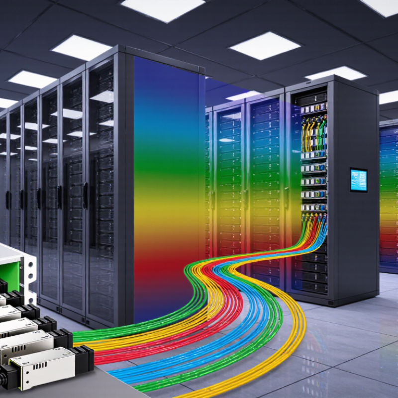
Why Choose CWDM Transceivers for Your Network?

Define CWDM: ITU-T G.694.2 specifies 20 nm channel spacing

Coarse Wavelength Division Multiplexing, or CWDM, combines several optical signals on one fiber. ITU-T Recommendation G.694.2 specifies a 20 nm channel spacing grid. Typical channels occupy wavelengths from 1271 nm to 1611 nm. This wide spacing simplifies wavelength management and reduces interference risks. It also supports practical metro links without dense cooling systems. According to the International Telecommunication Union’s Facts and Figures 2023, 5.4 billion people were online worldwide. More users create steady pressure on access and data-center networks. CWDM can add capacity without installing another fiber pair.

The value is visible in the rack. One fiber pair can carry several services, while transceivers remain relatively simple. Many deployments use uncooled lasers, which can lower power demand and equipment complexity. Reach often approaches 40 to 80 kilometers, depending on fiber quality, optical loss, and module specifications. The ITU’s Global Connectivity Report 2022 found that 95% of the world’s population lived within mobile broadband coverage. Coverage alone does not guarantee strong performance. Transport networks still need affordable upgrades. CWDM suits that gap, especially for campus, metro, and access aggregation. It is not a universal answer. Longer routes, tighter channel plans, or higher capacity may require another architecture. I would verify link budgets carefully; a convenient 20 nm grid does not remove engineering mistakes.

Calculate Capacity: 18 channels at 10 Gb/s provide up to 180 Gb/s

Why Choose CWDM Transceivers for Your Network?

CWDM transceivers can expand network capacity without installing a separate fiber pair for every service. Their main advantage becomes clear through channel planning. Eighteen channels operating at 10 Gb/s each can provide up to 180 Gb/s of combined line capacity. That figure is easy to verify: 18 × 10 equals 180. It gives network engineers a practical starting point for growth forecasts.

The calculation is clean. Real networks are less perfect. Protocol overhead, protection paths, inactive channels, and equipment limits can reduce usable throughput. A 180 Gb/s design may not deliver 180 Gb/s to applications. Careful testing matters. I have seen projects reserve several channels for future expansion, yet consume them quickly after traffic growth exceeded estimates. A simple spreadsheet is useful, but it should not replace measurements.

CWDM transceivers also support gradual deployment. An operator can activate four or six channels first, then add capacity as demand increases. This approach can reduce initial hardware costs and simplify maintenance. Channel spacing, optical power, connector quality, and fiber distance still require verification. Short links may perform differently from long metropolitan routes. Check the optical budget. Check it again. Compatibility testing between transceivers and switching equipment is equally important. Engineers should document actual throughput, temperature behavior, and fault recovery before approving the full 18-channel plan.

Check Distance: CWDM transceivers commonly support 10–80 km links

Why Choose CWDM Transceivers for Your Network?

CWDM transceivers commonly support links from 10 to 80 km. The actual distance depends on fiber quality, wavelength, connector loss, and optical power budget. A 40 km rating is not a promise for every route. I have seen links fail early after poorly measured patch panels were added. The fiber path matters more than the product label.

ITU-T G.694.2 defines the CWDM wavelength grid used for practical optical multiplexing. It supports several channels over one fiber pair, helping operators delay costly fiber construction. The 2023 edition of a widely cited Annual Internet Report estimated global IP traffic at 396 exabytes per month by 2022. That growth makes efficient metro connectivity increasingly important. Still, CWDM is not automatically the best choice. Dense traffic, tight latency targets, or future capacity plans may justify another architecture.

Tips: Measure the complete optical budget before ordering. Include splice loss, connector loss, and about 3 dB of engineering margin. Check the transceiver’s reach at your exact wavelength. A link near 80 km deserves field testing. Do not trust distance alone. Examine dispersion, temperature, and maintenance access. A shorter, cleaner route can outperform a longer theoretical design. Mistakes happen when planning assumes perfect fiber.

CWDM Transceiver Reach by Link Class

CWDM transceivers are commonly available for link distances from 10 km to 80 km. The actual achievable distance depends on fiber quality, connector loss, optical budget, and network conditions.

Compare Optics: CWDM’s 20 nm spacing exceeds DWDM’s 0.8 nm grid

CWDM transceivers use 20 nm channel spacing, giving each wavelength a wide optical lane. DWDM commonly uses a much tighter 0.8 nm grid. That difference affects design, installation, and maintenance in practical ways.

A wider gap allows more tolerance for wavelength drift and filter variation. Technicians can also identify channels more easily during fiber testing. In a campus link, four or eight CWDM channels may carry separate services over one fiber pair. The equipment usually needs fewer precision components, which can reduce deployment cost and simplify spare planning. Less complexity helps.

However, CWDM offers fewer channels and shorter reach than dense systems. A network carrying many 100G or 400G services may outgrow its available spectrum. Power budgets also need careful checking, especially across passive multiplexers, patch panels, and aging fiber. A 20 nm grid does not remove these losses. It only creates more wavelength room.

Field planning should include connector inspection, optical-power measurements, and temperature data from the transceivers. Environmental changes can still influence performance. Some designs look efficient on paper but leave little headroom after repairs or future links. That is a common weakness. CWDM suits moderate capacity and cost-sensitive routes, while tighter DWDM spacing fits high-density backbone growth. The right choice depends on channel demand, reach, and how much operational complexity the team can reliably support.

Select Applications: Use CWDM for metro, campus, and 5G networks

Why Choose CWDM Transceivers for Your Network?

Select Applications: Use CWDM for Metro, Campus, and 5G Networks

CWDM transceivers suit networks that need more capacity without installing new fiber. A passive multiplexer combines several wavelengths on one pair of fibers. Common CWDM grids span 1270 to 1610 nanometers. This approach can support metro links between buildings, campuses, and aggregation sites.

In a campus deployment, one fiber pair may connect a data center, laboratory, and administration building. Each service can use a separate wavelength. Installation becomes cleaner, while spare fiber remains available for growth. Link distance depends on optic power, connector loss, and fiber quality. Do not trust distance labels alone.

Metro networks benefit from simple wavelength expansion. A new service may need only another transceiver pair and careful power planning. CWDM also fits some 5G fronthaul and midhaul designs, especially where remote radio sites connect to centralized equipment. Timing and latency still require attention. Optical capacity is not the whole design.

Field testing often reveals small problems. Dirty connectors can erase the expected margin. Unequal path lengths can also complicate troubleshooting. CWDM is not a universal fix. Dense traffic growth may eventually require DWDM or additional fiber. Engineers should verify wavelength compatibility, insertion loss, dispersion limits, and monitoring requirements before deployment. A short pilot link can expose weaknesses early. That step is often skipped.

Why Choose CWDM Transceivers for Your Network? - Select Applications: Use CWDM for Metro, Campus, and 5G Networks

Network Application Typical Fiber Span Common CWDM Capacity Typical Wavelength Use Primary Benefits Key Design Considerations
Metro Networks Approximately 10–40 km, depending on fiber loss, connectors, splices, and optical power budget Up to 18 nominal channels on the standard CWDM wavelength grid; the usable number depends on the equipment and link budget 1271–1571 nm channels with 20 nm spacing are commonly specified for CWDM systems Adds multiple services over existing fiber, reduces the need for new cable installation, and supports gradual network expansion Verify fiber type, channel attenuation, dispersion, connector loss, and interoperability across optical modules and multiplexers
Campus Networks Approximately 2–10 km in many building-to-building or site-to-site deployments Often 2–8 channels are sufficient for separate data, security, voice, storage, and management services Individual wavelengths can be assigned to different switches, buildings, departments, or services Improves fiber utilization, simplifies service separation, and provides a scalable alternative to installing additional fiber pairs Consider building-entry procedures, fiber-route diversity, power availability, connector cleanliness, and future channel requirements
5G Transport and Fronthaul Commonly several kilometers to around 20 km; the actual distance varies with the radio architecture and transport design Multiple 10 Gb/s or higher-rate optical links can be carried on separate CWDM wavelengths, subject to equipment specifications Different wavelengths can connect radio units, distributed units, aggregation sites, and mobile transport nodes Supports fiber sharing, reduces cabling pressure at aggregation points, and enables flexible capacity allocation for distributed sites Validate latency, synchronization, optical reach, temperature range, insertion loss, and compatibility with the selected 5G transport architecture

Planning note: Actual reach and channel count depend on transceiver type, fiber attenuation, optical power budget, passive component loss, connector quality, operating temperature, and the required data rate.

FAQS

What distance can CWDM transceivers commonly support?

They commonly support 10–80 km links. Actual reach depends on fiber quality, wavelength, connector loss, and optical power.

Is a 40 km rating guaranteed on every fiber route?

No. A 40 km rating is not a promise. Poor patch panels, splices, or aging fiber can cause earlier failure.

What should be included in an optical budget?

Include fiber loss, splice loss, connector loss, and about 3 dB of engineering margin. Measure the complete route.

Why does CWDM use wider channel spacing?

CWDM commonly uses 20 nm spacing. The wider gaps tolerate more wavelength drift and filter variation.

How many services can one CWDM fiber pair carry?

Four or eight channels may carry separate services over one fiber pair. Capacity depends on the selected equipment and wavelengths.

Is CWDM suitable for every network?

No. It suits moderate capacity and cost-sensitive routes. Dense traffic or major future growth may require another design.

What losses can passive components introduce?

Multiplexers, patch panels, connectors, and splices can reduce available power. Small losses accumulate quickly.

What should technicians test before activating a long link?

Inspect connectors, measure optical power, check wavelength reach, and review temperature data. Test routes near 80 km in the field.

How can temperature affect CWDM links?

Temperature changes can influence transceiver performance and wavelength stability. Environmental data should be checked during planning.

What is a common planning mistake?

Assuming perfect fiber. A shorter, cleaner route may outperform a longer theoretical design. I would recheck every assumption.

Conclusion

CWDM transceivers provide a practical and cost-effective way to expand network capacity by carrying multiple wavelengths over a single fiber pair. Under the ITU-T G.694.2 recommendation, CWDM uses 20 nm channel spacing, allowing up to 18 channels. When each channel operates at 10 Gb/s, the system can deliver a potential aggregate capacity of 180 Gb/s. This broad spacing also simplifies optical design and typically lowers equipment complexity compared with denser wavelength systems.

A CWDM transceiver commonly supports link distances from approximately 10 to 80 km, depending on the optical budget and network conditions. Its 20 nm wavelength grid is considerably wider than the 0.8 nm spacing associated with DWDM, making CWDM easier to deploy for moderate-capacity applications. It is especially suitable for metropolitan networks, campus connectivity, and 5G transport, where operators need scalable bandwidth, straightforward installation, and reliable performance without the complexity of high-density long-haul systems.

Madeline

Madeline

Madeline is a dedicated marketing professional with a wealth of expertise in our company's core offerings. With a keen understanding of the industry, she brings a unique perspective to her role, consistently delivering high-quality content that highlights the superior aspects of our products. As......